Self-priming pump options
API 610 and self-priming pumps
Specifications sometimes call for an API 610 self-priming pump, however there is no such API standard for selfpriming pumps. The API 610 standard can only refer to the pump (e.g. OH1 or OH2) and this must be integrated with a (non-API 610) priming unit which is most cases will be operating in hazardous areas and so need to be ATEX compliant.
What is a self-priming pump?
Centrifugal pumps operate on flooded suction lines or in submersible applications. The impeller is surrounded by enough process fluid to create the pressure differential and thus to pump the fluid. However, when a standard centrifugal pump encounters air, it can become air-bound. It's much harder to pump air than to pump fluid, so when the air enters the pump it won't pump the fluid until the air can be removed in some way. The fluid moving through the pump is also used to keep it cool and lubricate moving parts and so a pump that has air in it can overheat causing seal damage, leakage and possible catastrophic failure as the small amount of fluid in the casing is effectively recirculated and rapidly heated. Additionally, if the pumped fluid is volatile, then air in the pump can become an explosive mixture as it heats up and so for volatile fluids, air in the pump must be minimised.
When a pump is started there may be air in the system. In some applications, such as lifting sea-water onto an offshore platform, a large amount of this air must be displaced in the pipework before the fluid reaches the pump. A self-priming centrifugal pump overcomes this problem, removing air from the system and ensuring the impeller chamber is full of fluid, or primed. A self-priming pump should also be able to prime itself when it is switched on without any other operator intervention.
Traditional self-priming casing pumps
With self-priming casing pumps, during the priming cycle, air enters the pump and mixes with the fluid at the impeller (Figure 1 – first diagram). The fluid and air are discharged together by centrifugal action of the impeller into a reservoir designed as an integral part of the pump. The air naturally tends to rise, while the fluid tends to sink by gravity back down into the impeller chamber, ready to mix with more air coming in the suction line. Once all air has been evacuated and a vacuum created in the suction line, atmospheric pressure forces the fluid up into the suction line towards the impeller, and pumping begins (Figure 1 – second diagram).
During the priming process in this sort of pump however, the process fluid becomes heated in the pump and so this method of priming cannot be used with a volatile process fluid or in a hazardous application, such as some duties on an offshore platform. In addition, traditional self-priming pumps usually have one-way foot valve in the process fluid to minimise fluid loss from the pipework when the pump is stopped, however these can be prone to failure, particularly in environments where solids may be present such as in the oil and gas industry, causing priming issues at the pump.
Traditional self-priming pumps can never conform to API 610.
Fluid retention methods
To overcome the problems inherent in traditional self-priming casing pumps, fluid retention methods are sometimes deployed separate to the API 610 pump. This involves fitting some means to ensure that the pumped fluid is retained in the casing whenever the pump is stopped so that it will be fully primed for the next start-up. It is essential to ensure that such a system is free of leaks to prevent dry running and any consequent damage to the pump mechanical seals and internals.
Foot valve
A simple method of keeping a suction lift pump primed is to fit a foot valve and strainer to the suction pump inlet which is always fully submerged. When the pump is stopped, the valve shuts off any reverse flow to keep the pump casing and suction pipework full of fluid. The disadvantage of this approach is that there will always be a pressure drop across the valve which may become critical if the strainer becomes blocked. Furthermore, some inevitable seepage through the valve will gradually drain the pump so that it will require refilling before it can be started and so some type of control system may be required to ensure that the pump is not run dry.
Suction interceptor
Another method of retaining fluid in the pump is to fit a suction interceptor. This consists of a simple collection tank attached to the pump suction. With this method, no foot valve is required. The inceptor inlet in positioned above the pump so that after the initial fill the interceptor will retain the pumped fluid each time the pump is stopped. When the pump is restarted, the retained fluid is delivered through the pump creating a pressure drop in the interceptor thereby drawing more fluid from the source. However, if using this method, it is critical that the interceptor is correctly sized so that the source fluid enters the interceptor before the retained fluid is pumped out otherwise the pump will start running dry. The startup time to ensure the pump is primed can be some 10 minutes for larger units and furthermore, if the pumped fluid contains solids these will settle in the interceptor and must be removed regularly otherwise the volume of fluid will be lowered leading to dry running of the pump.
Air evacuation and vacuum methods
This method involves using a vacuum device to remove all the air from the pump and suction pipework so that the pump is full of fluid before it is started. For simple installations with infrequent start-up this could be an inexpensive manually operated priming vacuum pump. However, this is labour intensive and time consuming and so not practical for most large-scale processes.
However, an alternative method of removing air from the pump and pipework is to fit a vacuum priming unit to the suction pipework above the level of the pump. The priming unit uses a vacuum pump or air injector to generate the vacuum and a control system to switch the unit on and off as necessary when the pump is running to maintain the fluid level above the pump to ensure it can never run dry.
Amarinth has used vacuum technology to develop a reliable and cost-effective solution for self-priming of API 610 pumps that is fully ATEX compliant without having any of the issues outlined in the other methods.
Amarinth self-priming pumps
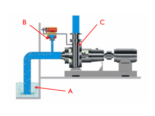
An Amarinth self-priming pump does not require a special priming chamber and so the pump is supplied as a standard API 610 (or ISO) pump (Figure 2 - C) and a primary unit (Figure 2 - B) to create the priming action is positioned just upstream of the pump – see Figure 1.
When process fluid needs to be pumped (Figure 2 - A), the primary unit (Figure 2 - B) first expels the air from the pipework thereby lifting the process fluid to the pump (Figure 2 - C) to prime it. The centrifugal pump (Figure 2 - C) is automatically switched on when the process fluid has fully primed the pump after which the primary unit (Figure 2 - B) is switched off.
The Amarinth primary unit uses an ejector which creates a vacuum in the pipe thereby lifting the process fluid to the pump. The primary unit ejector exploits the venturi effect by using air or process fluid and so has very few parts to fail or overheat. The design is therefore ATEX compliant and suitable for hazardous areas.
There is also no need to have a foot valve in the system as the primary unit is always capable of lifting the process fluid to the pump regardless of the air in the system and the pump will only start when properly primed. However, a one-way foot valve can be used if desired to hold the process fluid in the inlet pipe when the pump is switched off in order that the primary unit (Figure 2 - B) has less air to expel and so speed up the start-up of the centrifugal pump (Figure 2 - C).
The maximum lift for an Amarinth self-priming pump is 7m (to the primary unit) and the only utilities required are air or fresh water for the ejector and an electrical supply for the primary unit, pump, instrumentation and controls.
Amarinth self-priming units are modular and flexible. A bespoke unit, fully integrated by Amarinth with the API 610 pump, can be optimised for the duty and delivered quickly and cost-effectively. The material the priming unit is manufactured from can be specified for the particular process fluid and could be the same material as the pipework or even the pump. The modular approach also ensures that key components in the priming unit can be interchanged to suit customer specific Approved Vendor Lists.
Summary
The following table summarises the benefits and operating parameters of Amarinth self-priming design against those of traditional self-priming pumps.
| Amarinth self-priming design | Traditional self-priming designs |
|---|---|
| The pump meets API 610 standards by using a separate self-priming unit upstream of an API 610 pump | A pump with an integral self-priming chamber does not meet API 610 standards |
| Can be used in hazardous applications (ATEX compliant) | Self-priming casing pumps cannot usually be used in hazardous applications |
| Can be used with a volatile process fluid as no heating of the fluid happens during priming | Self-priming casing pumps can only be used with a nonvolatile process fluid as it will be heated during priming |
| Pump does not start until primary unit has fully primed it and so the pump can never run dry | Self-priming casing pumps start immediately and if they don’t prime correctly can run dry; foot valves suffer from leakage |
| No external flaps or valves are necessary in the process fluid to become jammed by solids | Foot valves may jam or fail when solids are present in the process fluid and the strainers may become blocked; suction interceptors can lose volume due to solids build-up causing the pump to run dry |
| Maximum lift 7m | Maximum lift 7m |
Available for download in PDF format, simply click the button below to download.
Download File