API 610 performance curve criteria for VS4 vertical sump pumps
Selecting the Right Pump
Vertical sump pumps present a unique challenge in selecting the right pump for the duty. The difference between the top of a tank (pump discharge) and where the pump and impeller (pump centre line) is actually sited maybe more than 10m apart, which can be a significant proportion of the head required.
This leads to potential confusion and mis-selection if it is not clear where the duty datum is calculated from. For example, the pump manufacturer may think the customer’s datum is the top of the discharge flange (the pump discharge datum) but the customer is calculating the performance based on the impeller centreline (pump centreline datum in Figure 1). This could easily lead to the selected pump generating too little head, or vice versa if the opposite assumptions are made.
The length of the vertical pump itself also has an impact on the performance curve due to variable losses in the pump. Each line bearing absorbs a small amount of power and so the number of bearings must be taken into account. The longer the pump the more line bearings and therefore the greater the power losses which need to be allowed for in the motor selection.
The seal arrangement will also create power losses in the pump. A double mechanical seal can lose in the region of 1-2 kW whereas the losses in a lipseal would be negligible. The seal losses may not sound significant but when added to the line bearing losses on a small pump they can be a critical factor in selecting the correct motor for the pump.
Lastly, the pump will need to maintain lubrication to the line bearings to prevent catastrophic failure. The most common option is to take some of the fluid generated by the pump and recirculate it through the bearings. These head and flow losses therefore also need to be allowed for in the calculation depending on where the customer’s datum is taken from.
Alleviating Pump Selection Issues
To alleviate these issues, Amarinth can provide two performance curves to help customers select the right pump – see Figures 2 and 3. The first is at the pump centreline and the second is at the pump discharge which is located at the top flange. It should be noted that the performance curve for the pump discharge at the top flange is at the point the external pipework is bolted to the flange, not at the top plate. The pump discharge performance curve takes into account the length of the pump and any losses due to line bearing recirculation and pipework.
In summary, when working with a customer to select the optimum vertical pump for a duty, it must be clarified where the customer is basing their data for flow and head – the pump centreline or the discharge flange, and the appropriate performance curve must be selected to match this data.
Optimum vertical pump datum
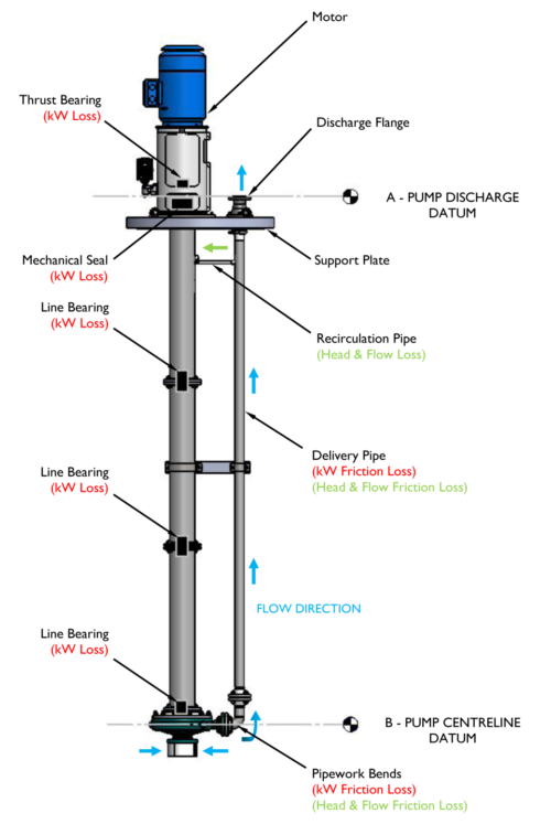
1. Pump length can be greater than 10m.
2. If customer’s datum is at pump discharge (A), the pump length plus recirculation and pipe losses, bearing losses and seal losses have to be added back to calculate pump head and flow needed at the impeller centre line.
3. If customer’s datum is at pump centreline (B), the customer will not know the recirculation or pipe losses so these need to be added on to the generated head and flow – only the pump manufacturer will know this detail.
Centreline pump performance curves
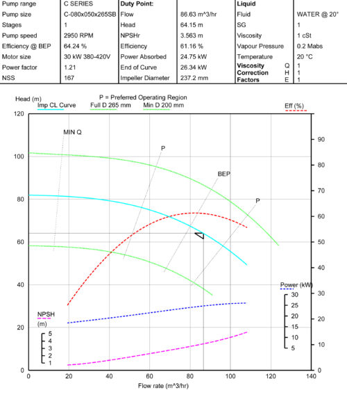
Figure 2: Centreline pump performance curves for C-080x050x265SB pump showing 64m head at pump impeller centreline
Discharge flange performance curves
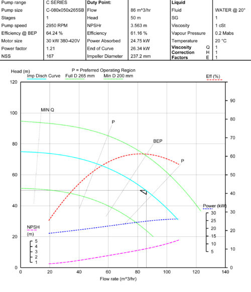
Figure 3: Discharge flange performance curves for C-080x050x265SB pump showing reduction to 50m head at pump discharge
The two graphs in Figure 2 and Figure 3 are for exactly the same pump and duty. Figure 2 is at the impeller centre line and Figure 3 at the discharge flange. Looking at the differences in the curves, for the same flow rate of 85m3/hour, when measured at the impeller centre line the pump will generate a head of 64m, but when measured at the discharge, only 50m.
Adjustments to be made between discharge flange and pump centreline
The adjustments needed to calculate the differences for head, flow and power between the pump discharge datum (A) and the pump centreline datum (B) are shown in the table below.
To start from the pump discharge flange (A) and calculate the equivalent pump centreline datum (B) figures, you need to add the relevant values in the table.
To start from the pump centreline datum (B) and calculate the equivalent pump discharge flange (A) figures, you need to subtract the relevant values in the table.
However, in general, it is best for the customer to give the required duty at the discharge flange and then let the manufacturer calculate the pump required as many of the losses are empirical and only known by the manufacturer.
| At discharge flange (datum A) | Head (m) | Flow (m3/h) | Power (kW) |
|---|---|---|---|
| Length of pump | +/- ad | ||
| Bearing flush recirculation losses | +/- ad | +/- ad | +/- ad |
| Pipe work frictional losses | +/- ad | +/- ad | |
| Line bearing losses | +/- ad | ||
| Seal losses | +/- ad | ||
| At pump centreline (datum B) | Head (m) | Flow (m3/h) | Power (kW) |
Available for download in PDF format, simply click the button below to download.
Download File