An explanation of API 610 centrifugal pump configurations
In this document we explain centrifugal pump terminology and the API 610 pump configurations. API is the abbreviation for American Petroleum Institute which is the main U.S trade association for the oil and natural gas industry representing organisations involved in producing, refining, distributing, and many other aspects. Centrifugal pumps are one of the most common categories of rotating equipment found in these industries and the American Petroleum Institute created the API 610 standard for these pumps.
API 610 classifies various types of centrifugal pumps which are primarily divided into three groups: OH, BB and VS.
OH – Overhung pumps – The impellers of these pumps overhang a radial bearing and so the support must take care of all forces, including the overhung mass and the rotor dynamic and hydraulic forces.
BB – Between bearing pumps – The impellers of these pumps are suspended between the two supports with the impeller placed horizontally, in the same orientation as the bearings.
VS – Vertically suspended pumps – The casing and impellers of these pumps are submerged in the pumped fluid, suspended on a vertical column below a support plate at the top of the tank to which the motor and thrust bearing are mounted.
Typical applications for these three types of API 610 pumps are:
OH – Overhung pumps: Produced Water; Feed Pump; Booster Pump; Hydrocarbon Transfer; Condensate
BB – Between bearing pumps: Cooling Water; Boiler Feed; Well Injection; Feed Water; Crude Transfer
VS – Vertically suspended pumps: Open Drain; Closed Drain; Crude Oil Transfer; Firewater; Seawater Lift
Terminology
There is a lot of terminology used for API 610 pumps, some general for all API 610 pumps and some specific to OH, BB or VS pumps. The following details the terminology that is used in describing each of the pumps in the later sections.
| Terminology | Applicability | |||
|---|---|---|---|---|
| OH | BB | VS | ||
| Installation | ||||
| Horizontal | The pump is designed to be installed parallel to level ground. | • | • | |
| Vertical | The pump is designed to be installed perpendicular to level ground. | • | • | |
| Mounting | ||||
| Foot-mounted | The pump casing is provided with feet designed for fastening the pump onto a foundation or base plate. | • | • | |
| Centerline supported | The pump is supported on the centerline of the casing providing for even thermal expansion on each side of the pump casing support enabling greater nozzle load capability than a foot-mounted casing. | • | • | |
| Plate mounted | The pump is fixed to a suitably sized and rated plate that is mounted on a tank and the wetted end of the pump in the fluid in the tank or sump. | • | ||
| Coupling | ||||
| Flexible | The coupling that transmits torque from one shaft to another is designed with some flexibility and so can accommodate small angular and parallel misalignment, reduce vibration and prolong the working life of the pump. | • | • | • |
| Rigid | The coupling that transmits torque from one shaft to another has no flexibility, the shafts are bolted rigidly together, which enable precise shaft alignment, however any misalignment will negatively impact pump performance and life. | • | • | • |
| Drive method | ||||
| Long coupled | A separate bearing bracket is attached to the pump housing and the motor is usually mounted on a support or baseplate. | • | • | |
| Close coupled | The pump is directly mounted to the motor shaft with all forces being taken care of by the bearings in the motor. | • | ||
| High-speed integral geared | The pump is installed with an integral speed-increasing gearbox. | • | • | |
| Lineshaft | The drive element between the motor and the impeller is supported by intermediate and lower bearings in a column within the fluid in the tank or sump. | • | ||
| Cantilever | Only the impeller and casing are submerged in the fluid in the tank or sump and all joints, including seals, bearings, bushings, and suction check valves, are located above the tank level out of the fluid with no intermediate shaft support. | • | ||
| Casing | ||||
| Single casing | The part of the pump that includes the impeller chamber and volute / diffuser, the single case contains the pumping pressure. | • | • | • |
| Double casing | A separate additional case surrounding the inner single case (that contains impeller chambers and volute / diffuser). The double casing can contain higher pressure than a single case and is frequently used with multistage pumps. | • | • | |
| Axially split | A split pump casing with the principal joint parallel to the shaft centerline. | • | ||
| Radially split | A split pump casing with the principal joint perpendicular to the shaft centerline. | • | • | • |
| Diffuser | A set of stationary vanes / channels fitted in a diffuser casing / ring that convert velocity into pressure energy, they also guide the fluid to the impeller vanes of the subsequent stage in a multistage pump. | • | • | • |
| Volute | A spiral-like form where liquid is discharged from the impeller into the volute casing. the volute areas increase at a rate proportional to the discharge of liquid from the impeller so that a constant velocity exists around the periphery of the impeller. | • | • | • |
| Impeller | ||||
| 1 and 2 stage | The pump has one or two impellers and sometimes diffusers all installed within a single volute casing. | • | • | • |
| Multistage | The pump has three or more impellers installed within a volute casing. | • | • | |
| Bowl assembly | This can be one or more stages and consists of the suction case or bell, impellers, and diffuser casings. All the impellers are mounted onto a single bowl shaft. | • | ||
| Axial flow | Pumped fluid is pushed in a direction parallel to the pump shaft, axial flow pumps can provide a higher flow rate but with a lower head compared to radial flow pumps. | • | • | • |
| Radial flow | Pumped fluid is pushed in a direction perpendicular to the pump shaft, radial flow pumps generate higher heads than axial flow pumps but with a lower flow rate also have less pressure drop as flow increases. | • | • | • |
| Discharge | ||||
| In-line | The discharge of the pump is arranged in the same plane as the suction for direct installation into the pipework. | • | • | • |
| Top | The discharge of the pump is arranged tangential to the vertical centreline. | • | • | • |
| Column | The discharge goes through the same support column as the driven shaft for the impeller. | • | ||
| Separate | The discharge goes through a separate pipe to the support column containing the driven shaft for the impeller. | • | ||
API 610 Pumps
API 610 divides centrifugal pumps into three groups: Overhung (OH), Between Bearings (BB) and Vertically Suspended (VS). The following section details the various configurations within each category.
OH
An API 610 OH pump is an “Overhung” pump where the impeller is mounted on the end of a shaft which is “overhung” from its bearing supports. The impellers of OH pumps can be mounted horizontally or vertically.
| Type | Installation | Mounting | Coupling | Drive | Discharge | Typical Applications | Image | ||||||
|---|---|---|---|---|---|---|---|---|---|---|---|---|---|
| Hor | Ver | Foot | CLine | Flex | Rigid | Long | Close | Gearbox | Inline | Top | |||
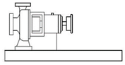
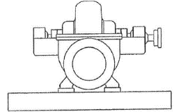
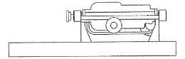
| OH1 | A flexibly long coupled horizontal, foot mounted, single stage, end suction, overhung pump. OH1 pumps, according to API 610 specifications, are long coupled, however Amarinth can also provide pumps that are close coupled. | Produced water MEG reclamation Boiler feed |
 |
||||||||||
| • | • | • | • | A | • | ||||||||
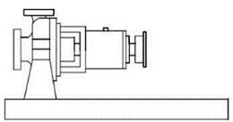
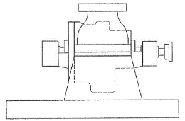
| OH2 | A flexibly long coupled horizontal, centerline mounted, single stage, end suction, overhung pump. OH2 pumps, according to API 610 specifications, are long coupled, however Amarinth can also provide pumps that are close coupled. | Amine Booster pump Fuel transfer |
 |
||||||||||
| • | • | • | • | A | • | ||||||||
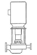
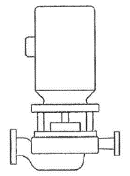
| OH3 | A flexibly long coupled vertical inline, single stage, overhung pump. The pump can be mounted to a support frame or within the pipeline. | Gas drum Sour water Sea water |
 |
||||||||||
| • | ⚬ | ⚬ | • | • | • | ||||||||
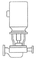
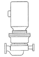
| OH4 | A rigidly close coupled vertical inline, single stage, overhung pump. The motor is mounted directly to the pump housing. The pump can be mounted to a support frame or within the pipeline. | Water injection Fuelling Crude oil pipeline |
 |
||||||||||
| • | ⚬ | ⚬ | • | • | • | ||||||||
| OH5 | A flexibly long coupled vertical inline, single stage, overhung pump. The pump can be mounted to a support frame or within the pipeline. | Hydrocarbon Oily water MEG water |
 |
||||||||||
| • | ⚬ | ⚬ | • | • | • | ||||||||
| OH6 | A horizontal or vertical, single stage, end suction overhung, pump that has an integral gearbox driven by the motor with a rigid coupling mounted to the pump housing. | High pressure feed Reverse osmosis Boiler feed |
 |
||||||||||
| ⚬ | ⚬ | ⚬ | ⚬ | • | • | • | • | ||||||
• = Standard
⚬ = Optional
A = Amarinth low cost option, only Long Coupled is strictly defined by API 610
BB
An API 610 BB pump is a “Between-bearings” pump where the impeller is mounted on a shaft with the bearings at both ends so the impeller is mounted between bearings. For all BB pumps the impeller is mounted horizontally.
| Type | Casing | Impeller | Typical Applications | Image | ||||
|---|---|---|---|---|---|---|---|---|
| Single | Double | Axial Split | Radial Split | 1/2 Stage | Multistage | |||
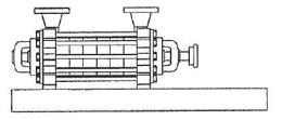
| BB1 | An axially split single casing, one or two stage pump with bearings on both ends of the rotating assembly. The pump is mounted to a baseplate and driven by a motor via a flexible coupling. | Cooling water Sea water transfer Produced water |
 |
|||||
| • | • | • | ||||||
| BB2 | A radially split single casing, one or two stage pump with bearings on both ends of the rotating assembly. The pump is mounted to a baseplate and driven by a motor via a flexible coupling. | Boiler feed Booster Petrochemical processing |
 |
|||||
| • | • | • | ||||||
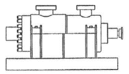
| BB3 | An axially split single casing, multistage pump with bearings on both ends of the rotating assembly. The pump is mounted to a baseplate and driven by a motor via a flexible coupling. | Water injection High pressure boiler feed Dewatering |
 |
|||||
| • | • | • | ||||||
| BB4 | A radially split single casing, multistage pump with bearings on both ends of the rotating assembly. The pump is mounted to a baseplate and driven by a motor via a flexible coupling. Sometimes called segmental-ring pump or ring-section pump. | Reverse osmosis High pressure boiler feed Feed water pump |
 |
|||||
| • | • | • | ||||||
| BB5 | A radially split double casing, multistage pump with bearings on both ends of the rotating assembly. The pump is mounted to a baseplate and driven by a motor via a flexible coupling. Sometimes referred to as “barrel pumps”. BB5 pumps can be made to handle very high pressures. | Offshore crude shipping Ethylene shipping Onshore & offshore water flood |
 |
|||||
| • | • | • | ||||||
• = Standard
VS
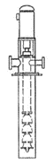
An API 610 VS pump is a “Vertically Suspended” pump where the casing and impeller is suspended below a support plate at the end of a vertically suspended support column and submerged into the fluid to be pumped.
| Type | Casing | Impeller | Discharge | Typical Applications | Image | |||||||
|---|---|---|---|---|---|---|---|---|---|---|---|---|
| Single | Double | Volute | Diffuser | Single | Multi | Axial | Radial | Column | Separate | |||
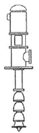
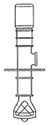
| VS1 | A vertically suspended diffuser pump with a single casing and an axial impeller with its discharge through the lineshaft column that suspends the bowl assemblies. The pump is mounted to a support plate and driven by a flexible coupling. | Sea water lift Pipeline transfer Condensate extraction |
 |
|||||||||
| • | • | ⚬ | ⚬ | ⚬ | • | • | ||||||
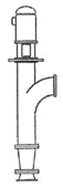
| VS2 | A vertically suspended volute pump with a single casing and an axial impeller with its discharge through the lineshaft column that suspends the casing. The pump is mounted to a support plate and driven by a flexible coupling. | Sea water intake Cooling water Loading & unloading |
 |
|||||||||
| • | • | • | ⚬ | • | • | |||||||
| VS3 | A vertically suspended volute pump with a single casing and an axial impeller with its discharge through the lineshaft column. The pump is mounted to a support plate and driven by a flexible coupling. | Raw water intake Water treatment Cooling water |
 |
|||||||||
| • | • | • | • | • | ||||||||
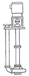
| VS4 | A vertically suspended, single stage, volute pump with a single casing and a radial impeller. The discharge column is separate to the lineshaft column. The pump is mounted to a support plate and driven by a flexible coupling. | Reverse osmosis High pressure boiler feed Feed water pump |
 |
|||||||||
| • | • | • | • | |||||||||
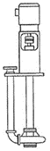
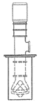
| VS5 | A vertically suspended, single stage, volute pump a single casing and a radial impeller. The discharge column is separate to the lineshaft column which is a cantilever design. The pump is mounted to a support plate and driven by a flexible coupling. | Slurry Water Treatment Solids handling |
 |
|||||||||
| • | • | • | • | • | ||||||||
| VS6 | A vertically suspended diffuser pump with a double casing and an axial impeller with its discharge through the lineshaft column that suspends the bowl assemblies. The pump is mounted to a support plate and driven by a flexible coupling. | Condensate extraction Pipeline booster Crude oil loading |
 |
|||||||||
| • | • | ⚬ | ⚬ | • | • | |||||||
| VS7 | A vertically suspended, volute pump with a double casing and an axial impeller with its discharge through the lineshaft column that suspends the bowl assemblies. The pump is mounted to a support plate and driven by a flexible coupling. | Pipeline booster Condensate Desalination |
 |
|||||||||
| • | ⚬ | ⚬ | • | • | ||||||||
• = Standard
⚬ = Optional
Available for download in PDF format, simply click the button below to download.
Download File